

|
FhSim
3.1.0
Marine systems simulation
|
|
|
FhSim
3.1.0
Marine systems simulation
|
 Collaboration diagram for Ship with advanced hull:
fhsim_maritime_issue_0065
fhsim_maritime_issue_0099

The FhSim ship model implements a time-domain realization of frequency domain hydrodynamics from frequency dependent added mass and dampening. The main source of frequency domain hydrodynamic data is computer codes based on potential theory such as VERES and WAMIT. The current model implementation only supports VERES data sets, but the implemented approach can be extended to WAMIT upon request.
The added mass and dampening of the vessel is represented as a linear time independent (LTI) companion system in a feedback loop with the rigid body dynamics of the vessel. The input to the companion system is the velocities of the vessel and the output is the dampening force from wave generation by the hull as the vessel oscillates. The time-domain realization is generated directly from result files of the frequency domain analysis by application of the "Vector fitting" system identification algorithm. The vector fitting algorithm is implemented internally in the ship model and the conversion from frequency to time-domain is computed on-line. The order of the LTI approximation of the fluid memory effect is chosen by comparing added mass and dampening reconstructed from the frequency response of the LTI-approximation with the original input data.

The structure of the seakeeping problem is used to generate a time-domain model. The seakeeping problem is studied by decomposing the forces acting on a harmonically oscillating vessel in harmonic waves into
The equations of motion of the vessel including the radiation force is derived by considering the equations of motion of the rigid body
\[ M_{rb}\ddot{\xi} = \tau \]
The excitation force is presumed to vary as a harmonic function and to be linearly independent. This results in linearly independent harmonic motions \(\xi=|\xi|sin(\omega t)\). The assumption of linearity allows the separation of the force \( \tau \) into the force from wave radiation, the restoring force and the excitation force from the waves
\[ \tau = \tau_{radiation} + \tau_{restoring} + \tau_{excitation}\]
The seakeeping problem can now be solved independently independently for the excitation force (the diffraction problem) and the radiation force while the restoring force acts as a linear spring force.
The radiation force can be expressed as:
\[ \tau_{rad}(\omega) = -A(\omega)\ddot{\xi} - \int_0^t K(t - t')\dot{\xi}dt' \]
The linear restoring force is expressed as
\[ \tau_{res} = G\xi \]
Substitution of the above expressions into the original equation and transferring it to the time domain yields the following equation named the "Cummins equation"
\[ (M+A_{\infty})\ddot{\xi} + \int_{0}^{t} K(t-t')\dot{\xi}dt'+G\xi = \tau_{excitation} \]
The Cummins equation contains a convolution integral which is cumbersome (but not impossible) to evaluate numerically as the time \(t\) increases. The convolution integral can be approximated by computing the frequency response of the \(K\) function and constructing an LTI system which approximates the frequency response.
\[ K(j\omega) = B(\omega) + j\omega (A(\omega) - \lim_{\omega \to \infty} A(\omega)) = \frac{P(j\omega)}{Q(j\omega)} \]
The coefficients of the rational transfer function \(\frac{P(j\omega)}{Q(j\omega)}\) is computed and transferred to a state-space representation which yields the final system of equations.
\[ (M+A_{\infty})\ddot{\xi}+X+G\xi = \tau_{excitation} \]
\[ \dot{\chi}=A_d\chi+B_d\dot{\xi} \]
\[ X = C_d\chi+D_d\dot{\xi} \]
The ship model includes calculation of external forces and internal dampening forces. All forces can be enabled/disabled and scaled through the appropriate interfaces.
The excitation forces included are mainly wave forces as well as hydrostatic restoring forces
The hydrostatic restoring force on the body
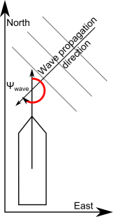
The first order wave force, or froude-krylov force, as experienced in the body frame of the vessel The first order wave loads are defined as a sum of harmonic functions with the same frequency distribution as the wave elevation.
\[ \tau_{1. order} = \sum_{n=0}^{n_{waves}}\zeta_n A(\omega_n,\psi_n,U) \cdot cos( \omega_{n} - k_n x + \epsilon_n) \]
The excitation RAO A is read at the forward speed U of the ship through the water (bilinear in speed and frequency, the speed held to the speeds of the data set, MAR-0092); the radiation model stays at zero speed.
The mean value of the higher order wave forces as experienced in the body frame of the vessel. The mean value of the heave, roll and pitch direction equals zero.
\[ \tau_{wave-drift} = \sum_{n=0}^{n_{waves}} {\zeta_{n}}^2 A(\omega_n,\psi_n,U) \]
The dampening force from wave generation by the vessel motions. This is the output of the "fluid memory" model
The viscous forces represent friction and vortex shedding which is not captured by the seakeeping problem which defined the potential dampening. The viscous forces are dampening forces and represents the effect of ship resistance in surge, cross flow drag in sway and yaw and vortex shedding in roll.
Viscous forces on body
The calm water resistance of the hull in the surge direction The resistance force is the defined as the calm water resistance of the hull. The calm water resistance is divided into the Reynolds number ( \( R_n\)) dependent friction contribution, and the Froude number ( \( F_n\)) dependent wave generation from the flow pattern around the hull. The resistance is calculated by scaling the dimensional total resistance coefficient, \( C_{ts}\), by the wet surface, \( S\), on the current waterline. The total resistance coefficient is both \( R_n\) and \( F_n\) dependent and is defined as.
\[ C_{ts} = (1+k) (C_f(R_n) + \Delta C_f(R_n)) + C_r(F_n) \]
Where
\[ R_{ts} = \frac{1}{2}\rho U^2 \cdot S \cdot C_{ts}\]
Astern: for a negative surge speed the resistance is evaluated at \(5|U|\) and acts against the motion, so it is about 25 times the resistance at the same speed ahead (owner decision, kept on purpose: the empirical curves are for ahead running only). The speed is limited to 100 m/s.
Cross flow are calculated by summation of section wise cross flow drag along the hull. Dampening in yaw is computed by calculating the moment contribution around the center of gravity for each sections cross flow drag force
\[ v_r = v-x\cdot r\]
\[ Y_{cross-flow} = -\frac{1}{2}\rho\int_{-Lpp/2}^{Lpp/2}T(x)C_d^2d(x)|v_r|v_r dx \]
\[ N_{cross-flow} = -\frac{1}{2}\rho\int_{-Lpp/2}^{Lpp/2}T(x)\cdot x\cdot C_d^2d(x)|v_r|v_r dx \]
The model supports additional user defined dampening forces. The forces are calculated from dimensionless dampening coefficients made dimensionless by \(m\) and by \(m\cdot L_{pp}\) for linear and rotational degrees of freedom respectively. The dampening force contains a linear and a quadratic modulus term which are controlled by separate dampening coefficients.
\[ F = C_{d_linear} \cdot m \cdot v + C_{d_quadratic} \cdot m \cdot v|v|\]
\[ M = C_{d_linear} \cdot m \cdot L_{pp} \cdot v + C_{d_quadratic} \cdot m \cdot L_{pp}\cdot v|v|\]
The dampening force decreases with increasing forward velocity by weighting the force with \(exp{-\frac{1}{2}|U|}\)
The parameters are read and checked in one function, ShipSimObject::ReadParameters, into the struct Ship::ShipParameters, which holds the default of each. A parameter that is given but cannot be read, or has an invalid value, is a named parameter error. Angles are in radians, lengths in metres, speeds in m/s.
| Name | Width | Description |
|---|---|---|
| PotentialFileLocation | 1 | The directory which contains the potential data in the frequency domain. Required @addoption{PotentialFileName, 1, The "stem" of the potential data filenames (the VERES files stem.hyd, stem.re2, stem.re7, stem.re8 and the hull file). Required} @addoption{PotentialType, 1, The type of potential data. Default "VERES". "WAMIT" is an error (not implemented), any other value is a parameter error} @addoption{FlipPhaseForOSC, 1, Flips the sign of the first order wave force RAOs read from the VERES data: 1 pitch, 2 roll and pitch, 3 or 4 roll, pitch and yaw, 5 all six degrees of freedom. Default 0 (no flip)} |
| ZeroSpeedRadiation | 1 | Constrain the fluid memory model to zero speed. Default true. false is a parameter error: the forward speed radiation model is not usable (MAR-0027) @addoption{NumWaveComponents, 1, Number of wave components the ship takes from the environment, the largest ones when there are more. Default 52. Must be at least 1} @addoption{ForceInput, 1, The list of force input ports on the ship, separated by comma or space: "NED" adds ForceNED and TorqueNED, "BODY" adds ForceBODY and TorqueBODY (upper or lower case). Default "NED"} @addoption{ForceScale, 8 or 11, Scale of each force term in the equation of motion. Used only when exactly 8 or 11 values are given: with any other count (also none) every scale is 1 without an error, and with 8 values the last three stay 1. The order is external force, first order wave force, wave drift force, viscous force (manoeuvring, DP and roll damping), user defined damping, fluid memory force, restoring force, cross flow force, resistance, Coriolis fluid force, Coriolis rigid body force.} |
| CoriolisRollOnly | 1 | Use only the roll component of the two Coriolis forces. Default false (all six components) |
| Name | Width | Description |
|---|---|---|
| alfaN | 1 | Initial rotation about the global north axis [rad]. Default 0 |
| alfaE | 1 | Initial rotation about the global east axis [rad]. Default 0 |
| alfaD | 1 | Initial rotation about the global down axis [rad]. The initial rotation is the product of the three. Default 0 |
| SurgeVelocity | 1 | Initial surge velocity of the vessel in the body frame [m/s]. Default 0 |
| Name | Width | Description @addoption{DOF0Free, 1, 1 lets surge move, 0 freezes it (its acceleration is zero). Default 1} |
|---|---|---|
| DOF1Free | 1 | The same for sway. Default 1 |
| DOF2Free | 1 | The same for heave. Default 1 |
| DOF3Free | 1 | The same for roll. Default 1 |
| DOF4Free | 1 | The same for pitch. Default 1 |
| DOF5Free | 1 | The same for yaw. Default 1 @addoption{StabilizeDOF0, 1, Negative feedback of the fluid memory states of surge, which pulls them to zero: the state derivative of the block (i,j) of the fluid memory model gets -StabilizeDOF*StabilizeDOF<j>*state. Default 0 (no feedback)} |
| StabilizeDOF1 | 1 | The same for sway. Default 0 |
| StabilizeDOF2 | 1 | The same for heave. Default 0 |
| StabilizeDOF3 | 1 | The same for roll. Default 0 |
| StabilizeDOF4 | 1 | The same for pitch. Default 0 |
| StabilizeDOF5 | 1 | The same for yaw. Default 0 |
| Name | Width | Description @addoption{WaveForceType, 1, Type of wave force: 0 potential theory RAOs (default), 1 integration of the undisturbed wave pressure over the wet surface} @addoption{WaveForceHFrame, 1, Decompose the wave forces in the frame that follows the yaw angle of the ship only (the "H frame", parallel to the still water surface) instead of the body frame. Default false} |
|---|---|---|
| WaveForceTransientTime | 1 | The time from the simulation start to 100 % wave force: the wave forces are ramped with 1-exp(-3 t/time) [s]. Default 0.1. Cannot be zero @addoption{HydroStaticsType, 1, Type of hydrostatic calculation: false linear restoring force (default), true integration over the wet surface} |
| HydroStaticsStationVerticalStep | 1 | The vertical separation of the elements of the wet surface and of the hull visualization [m]. Default 1 |
| HydroStaticsStationHorizontalStep | 1 | The horizontal separation of the same elements [m]. Default 1 |
| HydroStaticsStationTop | 1 | The vertical top coordinate of the same elements [m]. Default 15 |
| HydroStaticsStationBottom | 1 | The vertical bottom coordinate of the same elements [m]. Default -1 |
| Name | Width | Description |
|---|---|---|
| UseCrossFlow | 1 | Use the cross flow drag calculation. Default true @addoption{DamperLinear, 3, Linear damping coefficients of surge, sway and heave, made dimensionless by the mass. Default 0 0 0} @addoption{DamperQuadratic, 3, Quadratic damping coefficients of surge, sway and heave, made dimensionless by the mass. Default 0 0 0} @addoption{DamperRotLinear, 3, Linear damping coefficients of roll, pitch and yaw, made dimensionless by the mass and Lpp. Default 0 0 0} @addoption{DamperRotQuadratic, 3, Quadratic damping coefficients of roll, pitch and yaw, made dimensionless by the mass and Lpp. Default 0 0 0} @addoption{WakeFraction, 1, The wake fraction of the hull. Read and kept, but not used by the force calculation. Default 0} |
| DampingBlendSpeed | 1 | The speed [m/s] at which the fraction DampingBlendFraction of the manoeuvring damping has replaced the DP damping. Default 8 @addoption{DampingBlendFraction,1, The blend between the DP and the manoeuvring damping at DampingBlendSpeed, between 0 and 1 (below 1). Default 0.9} @addoption{ManoeuvreMinSpeed, 1, Smallest speed in m/s used in v/u and r Lpp/u of the manoeuvring damping (the Yv_man, Nr_man, ... terms); below it the speed is held to this value so the force stays bounded at rest. Default 0.1. Must be positive} |
| Yv_man | 1 | Manoeuvring coefficient of the sway force against v/u (dimensionless). Default 0 |
| Yr_man | 1 | Manoeuvring coefficient of the sway force against r Lpp/u. Default 0 |
| Nv_man | 1 | Manoeuvring coefficient of the yaw moment against v/u. Default 0 |
| Nr_man | 1 | Manoeuvring coefficient of the yaw moment against r Lpp/u. Default 0 |
| Yvd_man | 1 | Manoeuvring added mass coefficient of sway against the sway acceleration. Default 0 |
| Yrd_man | 1 | Manoeuvring added mass coefficient of sway against the yaw acceleration. Default 0 |
| Nvd_man | 1 | Manoeuvring added mass coefficient of yaw against the sway acceleration. Default 0 |
| Nrd_man | 1 | Manoeuvring added mass coefficient of yaw against the yaw acceleration. Default 0 |
| Xud_man | 1 | Manoeuvring added mass coefficient of surge against the surge acceleration. Default 0 |
| Xvr_man | 1 | Manoeuvring coefficient of the surge force against |v r| Lpp/u^2. Default 0 |
| Xrr_man | 1 | Manoeuvring coefficient of the surge force against (r Lpp/u)^2. Default 0 |
| Xvv_man | 1 | Manoeuvring coefficient of the surge force against (v/u)^2. Default 0 |
| Xvvvv_man | 1 | Manoeuvring coefficient of the surge force against (v/u)^4. Default 0 |
| Xu_dp | 1 | DP linear damping of the surge force against u [N s/m]. Default 0 |
| Xv_dp | 1 | DP linear damping of the surge force against v. Default 0 |
| Xr_dp | 1 | DP linear damping of the surge force against r. Default 0 |
| Yu_dp | 1 | DP linear damping of the sway force against u. Default 0 |
| Yv_dp | 1 | DP linear damping of the sway force against v. Default 0 |
| Yr_dp | 1 | DP linear damping of the sway force against r. Default 0 |
| Nu_dp | 1 | DP linear damping of the yaw moment against u. Default 0 |
| Nv_dp | 1 | DP linear damping of the yaw moment against v. Default 0 |
| Nr_dp | 1 | DP linear damping of the yaw moment against r. Default 0 |
| RollDampingTheory | 1 | Reynolds number theory of the roll friction damping: "ITTC" (default) or "SeaWAY" (any case). Any other value is a parameter error |
| RollDampingPeriodHorizon | 1 | Window in seconds of the roll amplitude (the largest |roll| of the last seconds) and the roll period of the ITTC friction coefficient. Default 2.75 sqrt(10) = 8.7 s; use about one roll period or more. Must be positive. Unit: seconds @addoption{BilgeKeelStartPosition, 1, Longitudinal start position of the bilge keels in the coordinates of the hull data (the code subtracts LCG) [m]. Default NaN: no bilge keels, also when start and end are equal. A range whose start or end has no hull station on each side of it (outside the stations, or in the first or last station interval) is a parameter error} @addoption{BilgeKeelEndPosition,1, Longitudinal end position of the bilge keels, as the start position [m]. Default NaN} |
| BilgeKeelHeight | 1 | The height of the bilge keel [m]. Default 0 |
| WithSkeg | 1 | Include the roll damping of a skeg when not 0. Default 0 |
| WithSkegLift | 1 | Include the lift damping of the skeg in the roll damping. Default false |
| SkegStartSection | 1 | First hull station of the skeg (integer). Default 5. Must be >= 0. The eddy damping is zeroed on the skeg stations only when WithSkeg is not 0 |
| SkegEndSection | 1 | Last hull station of the skeg (integer). Default 15. Must be >= SkegStartSection, and > SkegStartSection with WithSkegLift |
| SkegStartPoints | SkegEndSection-SkegStartSection+1 | Index of the first vertex of the skeg on each skeg station (integers). Default 42 27 24 24 24 24 24 26 27 29 35. Each must be >= 0 and <= its SkegEndPoints entry |
| SkegEndPoints | SkegEndSection-SkegStartSection+1 | Index of the last vertex of the skeg on each skeg station (integers). Default 49 on each of the 11 default stations. The hull needs more vertices than this on each skeg station when WithSkeg or WithSkegLift is set |
| WithHullLift | 1 | Include the lift damping of the hull in the roll damping. Default true @addoption{ResistanceFriction, 1, The friction part of the calm water resistance: "ittc" (the ITTC curve), "curve" (the table of ResistanceFrictionCurveX and Y) or "none" (default; any other value adds no friction curve). Any case} @addoption{ResistanceFrictionCurveX, 1, The abscissa of the friction curve, numbers separated by comma or space. Read when ResistanceFriction is "curve". Default empty} @addoption{ResistanceFrictionCurveY, 1, The ordinate of the friction curve, as many numbers as the abscissa. Read when ResistanceFriction is "curve". Default empty} @addoption{ResistanceResidual, 1, The wave making part of the calm water resistance: "hollenbach" (the Hollenbach curve), "curve" (the table of ResistanceResidualCurveX and Y) or "none" (default). Any case} |
| ResistanceResidualHollenbachNumRudders | 1 | Number of rudders. Required when ResistanceResidual is "hollenbach" |
| ResistanceResidualHollenbachNumBrac | 1 | Number of brackets. Required with "hollenbach" |
| ResistanceResidualHollenbachNumBoss | 1 | Number of bossings. Required with "hollenbach" |
| ResistanceResidualHollenbachNumThruster | 1 | Number of thrusters. Required with "hollenbach" |
| ResistanceResidualHollenbachDiamPropeller | 1 | Propeller diameter [m]. Required with "hollenbach" @addoption{ScaleResidualResistance, 1, Scale of the residual resistance, read with "hollenbach". Default 1} |
| ResistanceResidualCurveX | 1 | The abscissa of the residual resistance curve. Read when ResistanceResidual is "curve". Default empty |
| ResistanceResidualCurveY | 1 | The ordinate of the residual resistance curve. Read when ResistanceResidual is "curve". Default empty |
Read only in a build with visualization (FH_VISUALIZATION), in the render setup.
| Name | Width | Description |
|---|---|---|
| ShowForceArrows | 1 | Show the force and moments as arrows in the center of gravity. Default true |
| Material | 1 | The material used on the hull during visualization. Default empty |
| Mesh | 1 | The mesh used for the vessel during visualization. If empty the VERES hull data is drawn |
| Scene | 1 | The scene file for the vessel during visualization. If empty the VERES hull data is drawn @addoption{RenderType, 1, The type of hull rendering used: "Box", "Stations", "Sliced" or "Interpolated" (default)} |
| HideUntil | 1 | The time until which the ship is hidden [s]. Default 0 |
| NodeOffset | 3 | Offset of the render node of the hull [m]. Default 0 0 0 |
Which input ports exist is set by the parameter ForceInput.
| Name | Width | Description |
|---|---|---|
| ForceNED | 3 | (with "NED" in ForceInput) External force in global north-east-down reference frame (with "NED" in ForceInput) |
| TorqueNED | 3 | (with "NED" in ForceInput) External moment in global north-east-down reference frame (with "NED" in ForceInput) |
| ForceBODY | 3 | (with "BODY" in ForceInput) External force in local body fixed reference frame (with "BODY" in ForceInput) |
| TorqueBODY | 3 | (with "BODY" in ForceInput) External moment in local body fixed reference frame (with "BODY" in ForceInput) |
| Name | Width | Description |
|---|---|---|
| PositionNED | 3 |
The position of the center of gravity in the global "north-east-down" coordinate system |
| PositionAPNED | 3 |
The position of the intersection between the aft perpendicular, baseline in the global "north-east-down" coordinate system |
| PositionZeroCrossNED | 3 |
The position of the midpoint of the water plane at Lpp/2 in the global "north-east-down" coordinate system |
| VelocityNED | 3 |
The six-dof velocity vector for the center of gravity in the global "north-east-down" coordinate system |
| RotationBody | 3 |
The vessels roll, pitch and yaw angles in the local coordinate system. The yaw angle is relative to the north direction. |
| QuaternionNED | 4 |
The rotation quaternion of the body as w,x,y,z |
| EulerAnglesNED | 3 |
The rotation of the body as three Euler angles (z-x-z sequence, canonical angles of the unit quaternion) |
| OmegaNED | 3 |
The rotational speed of the ship in the global "north-east-down" coordinate system |
| VelocityBody | 6 |
The full velocity vector of the vessel in body coordinates |
| BodyForce | 6 |
The total force acting on the vessel |
| FirstOrderWaveBody | 6 | The first order wave force, or froude-krylov force, as experienced in the body frame of the vessel The first order wave loads are defined as a sum of harmonic functions with the same frequency distribution as the wave elevation. |
| WaveDriftBody | 6 | The mean value of the higher order wave forces as experienced in the body frame of the vessel. The mean value of the heave, roll and pitch direction equals zero. |
| CrossFlowBody | 6 |
Cross flow are calculated by summation of section wise cross flow drag along the hull. Dampening in yaw is computed by calculating the moment contribution around the center of gravity for each sections cross flow drag force \[ v_r = v-x\cdot r\] \[ Y_{cross-flow} = -\frac{1}{2}\rho\int_{-Lpp/2}^{Lpp/2}T(x)C_d^2d(x)|v_r|v_r dx \] \[ N_{cross-flow} = -\frac{1}{2}\rho\int_{-Lpp/2}^{Lpp/2}T(x)\cdot x\cdot C_d^2d(x)|v_r|v_r dx \] |
| UFluidMem | 6 |
The speed the fluid memory model sees: the velocity of the vessel relative to the ambient (current) velocity in the body frame, 6 values |
| SpeedInfo | 5 |
Information about the reference speeds in the potential data and the current speed of the vessel |
| CoriolisRigidBody | 6 |
Coriolis force of the rigid body mass and inertia tensors as formulated in the center of gravity |
| CoriolisFluidBody | 6 |
Coriolis force of the added mass and inertia tensors as formulated in the center of gravity |
| ViscousForceBody | 6 |
Viscous forces on body |
| ResistanceBody | 6 | The calm water resistance of the hull in the surge direction The resistance force is the defined as the calm water resistance of the hull. The calm water resistance is divided into the Reynolds number ( \( R_n\)) dependent friction contribution, and the Froude number ( \( F_n\)) dependent wave generation from the flow pattern around the hull. The resistance is calculated by scaling the dimensional total resistance coefficient, \( C_{ts}\), by the wet surface, \( S\), on the current waterline. The total resistance coefficient is both \( R_n\) and \( F_n\) dependent and is defined as. |
| AdditionalDampeningBody | 6 |
The model supports additional user defined dampening forces. The forces are calculated from dimensionless dampening coefficients made dimensionless by \(m\) and by \(m\cdot L_{pp}\) for linear and rotational degrees of freedom respectively. The dampening force contains a linear and a quadratic modulus term which are controlled by separate dampening coefficients. \[ F = C_{d_linear} \cdot m \cdot v + C_{d_quadratic} \cdot m \cdot v|v|\] \[ M = C_{d_linear} \cdot m \cdot L_{pp} \cdot v + C_{d_quadratic} \cdot m \cdot L_{pp}\cdot v|v|\] The dampening force decreases with increasing forward velocity by weighting the force with \(exp{-\frac{1}{2}|U|}\) |
| FluidMemoryForceBody | 6 |
Fluid memory forces on body |
| RelativeVelocityBODY | 6 |
The relative velocity of the ship relative to the ambient (current) velocity |
| RotationForceFrame | 4 |
Rotation body if constrained to move parallel to the still ocean surface |
| RestoringForceBody | 6 |
The hydrostatic restoring force on the body |
| ViscousRoll | 6 |
The viscous roll damping in its six components: 1) friction damping, 2) eddy damping, 3) lift damping, 4) bilge keel damping, 5) skeg damping, 6) skeg lift damping |
| DriftSpeed | 1 |
The speed over ground in the horizontal plane, the norm of the surge and sway velocity in the body frame |
| ExternalForceNED | 3 |
External force in NED |
| ExternalForceBody | 3 |
External force in Body |
 1.9.8