

|
FhSim
3.1.0
Marine systems simulation
|
|
|
FhSim
3.1.0
Marine systems simulation
|
 Collaboration diagram for Ship local connection:
The "LocalConnection" SimObject defines a body fixed point which travels and rotates with the parent body. The main application of a body fixed point is to measure the position, acceleration and velocities on a particular point on a rigid body, and to calculate provide position and velocity data for calculation of forces. The body fixed point can also be used to translate a force on a particular point to a force and torque pair which acts on the origin of the parent body.
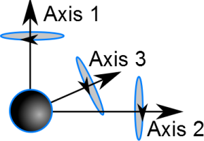
A Body fixed point defines a local coordinate system attached to the parent body. The initial orientation of the local coordinate system is a right handed system parallel to the axes of the parent body. The global orientation of the three axes can be obtained from the output and the relative orientation of the axes can be controlled form input ports. The rotation of the local coordinate system is defined as successive rotations about the first (x), second (y) and third axis (z).
| Name | Width | Description |
|---|---|---|
| ParentCGPositionNED | 3 |
Input port for the position of the CG and reference point body, required to calculate correct torque and velocities |
| ParentPositionNED | 3 |
The position of the parent body in north-east-down |
| ParentQuaternionNED | 4 |
The orientation quaternion of the parent body in north-east-down |
| ParentVelocityNED | 3 |
The linear velocities of the parent body in north-east-down |
| ParentOmegaNED | 3 |
The rotational speed of the parent body in north-east-down |
| ForceNED | 3 | Force in the NED frame. Only when ForceCalculator is true and ForceBody is false |
| ForceBody | 3 | Force in the parent body frame. Only when ForceCalculator is true and ForceBody is true |
| OffsetX | 1 | Target of the linear motor along x. Only when IsLinearMotor is true |
| OffsetY | 1 | Target of the linear motor along y. Only when IsLinearMotor is true |
| OffsetZ | 1 | Target of the linear motor along z. Only when IsLinearMotor is true |
| OffsetP | 1 | Target of the angular motor about axis 1. Only when IsAngularMotor is true |
| OffsetQ | 1 | Target of the angular motor about axis 2. Only when IsAngularMotor is true |
| OffsetR | 1 | Target of the angular motor about axis 3. Only when IsAngularMotor is true |
| Name | Width | Description |
|---|---|---|
| PositionNED | 3 |
The position in north-east-down coordinates |
| VelocityNED | 3 |
The Linear velocity in north-east-down coordinates |
| VelocityBody | 3 |
The velocity in the parents local axis system |
| OmegaNED | 3 |
The rotational velocity in north-east-down coordinates |
| QuaternionNED | 4 |
The rotation quaternion. The orientation quaternion is the rotation of the parent body rotated by any axis rotations of the 1,2,3 axes, in succession |
| Axis1NED | 3 |
The normal vector of the 1. axis in north-east-down coordinates |
| Axis2NED | 3 |
The normal vector of the 2. axis in north-east-down coordinates |
| Axis3NED | 3 |
The normal vector of the 3. axis in north-east-down coordinates |
| OffsetBody | 3 |
The offset of the connection point in local coordinates |
| RotationBody | 3 |
The Rotation of the connection point in local coordinates |
| ParentQuaternionNED | 4 | Quaternion of the parent body |
| ForceNED | 3 |
The force output in north-east-down coordinates |
| TorqueNED | 3 |
The torque output around the parent body origin of the force input in body coordinates |
| ForceBody | 3 | Force in the parent body frame. Only when ForceCalculator is true |
| TorqueBody | 3 | Torque in the parent body frame. Only when ForceCalculator is true |
| Name | Width | Description |
|---|---|---|
| LinearOffset | 3 | Offset of the point in the parent body frame. Required when IsLinearMotor is false |
| AngularOffset | 3 | Rotation angles of the local axes. Default 0. Used when IsAngularMotor is false |
| ForceCalculator | 1 |
Use the object to translate forces to force-torque pairs |
| ForceBody | 1 |
Set the input force in the parents body frame |
| ForceAttackOffsetBody | 3 | Where the input force acts in the parent body frame. Default 0 |
| IsLinearMotor | 1 | The linear offset is driven by the OffsetX, OffsetY and OffsetZ input ports |
| LinearMotorConstants | 3 | Motor constants of the linear motor. Required when IsLinearMotor is true |
| LinearMotorRateLimits | 3 | Largest rate of change of the linear offset. Default not set (NaN): no limit |
| IsAngularMotor | 1 | The rotation is driven by the OffsetP, OffsetQ and OffsetR input ports |
| AngularMotorConstants | 3 | Motor constants of the angular motor. Required when IsAngularMotor is true |
| AngularMotorRateLimits | 3 | Largest rate of change of the rotation angles. Default not set (NaN): no limit |
| AzimuthLoss | 1 | Apply an azimuth loss factor to the force. Default false: the factor is exactly 1 |
| AzimuthLossFactor | 2 | The two loss factors l0 and l1. Default 0.8 and 0.9. Used when AzimuthLoss is true: the force, ForceNED, ForceBody and the torques are multiplied by l0 cos^2(theta) + l1 sin^2(theta) with theta the yaw angle of the connection (AngularState[2]) |
| DrawConnection | 1 | Draw the connection in the visualization. Default true. Builds with visualization only |
| Scale | 1 | Scale of the sphere drawn at the connection. Default 0.1. Builds with visualization only |
The offsets are states so that a motor can move them. Without a motor the initial value is LinearOffset and AngularOffset (when the state is not set in the initial conditions).
| Name | Width | Description |
|---|---|---|
| LinearState | 3 | Offset of the point in the parent body frame |
| AngularState | 3 | Rotation angles of the local axes |
 1.9.8